


The Anatomy of Precision – Mechanics, Kinematics, and the Evolution of Machining
Meta Description: Dive deep into the mechanical differences between 3-axis and 5-axis CNC milling. In Part 1 of this guide by HYM Metal, we explore machine kinematics, trunnion vs. swivel configurations, and the physics of cutting forces.
1. Introduction: The Shifting Landscape of Manufacturing
In the contemporary landscape of industrial manufacturing, the "standard" is a moving target. What was considered high-precision aerospace technology twenty years ago is now the baseline expectation for general industrial components. As product designers utilize advanced CAD software to generate increasingly organic, aerodynamic, and ergonomic shapes, the manufacturing floor must evolve to keep pace.
For engineers and procurement managers, this evolution creates a persistent dilemma. You are tasked with sourcing parts that are more complex than ever, yet the pressure to reduce unit costs and shorten lead times has never been higher. This friction—between the desire for complex design and the constraint of budget—is where the choice of CNC machining services becomes critical.
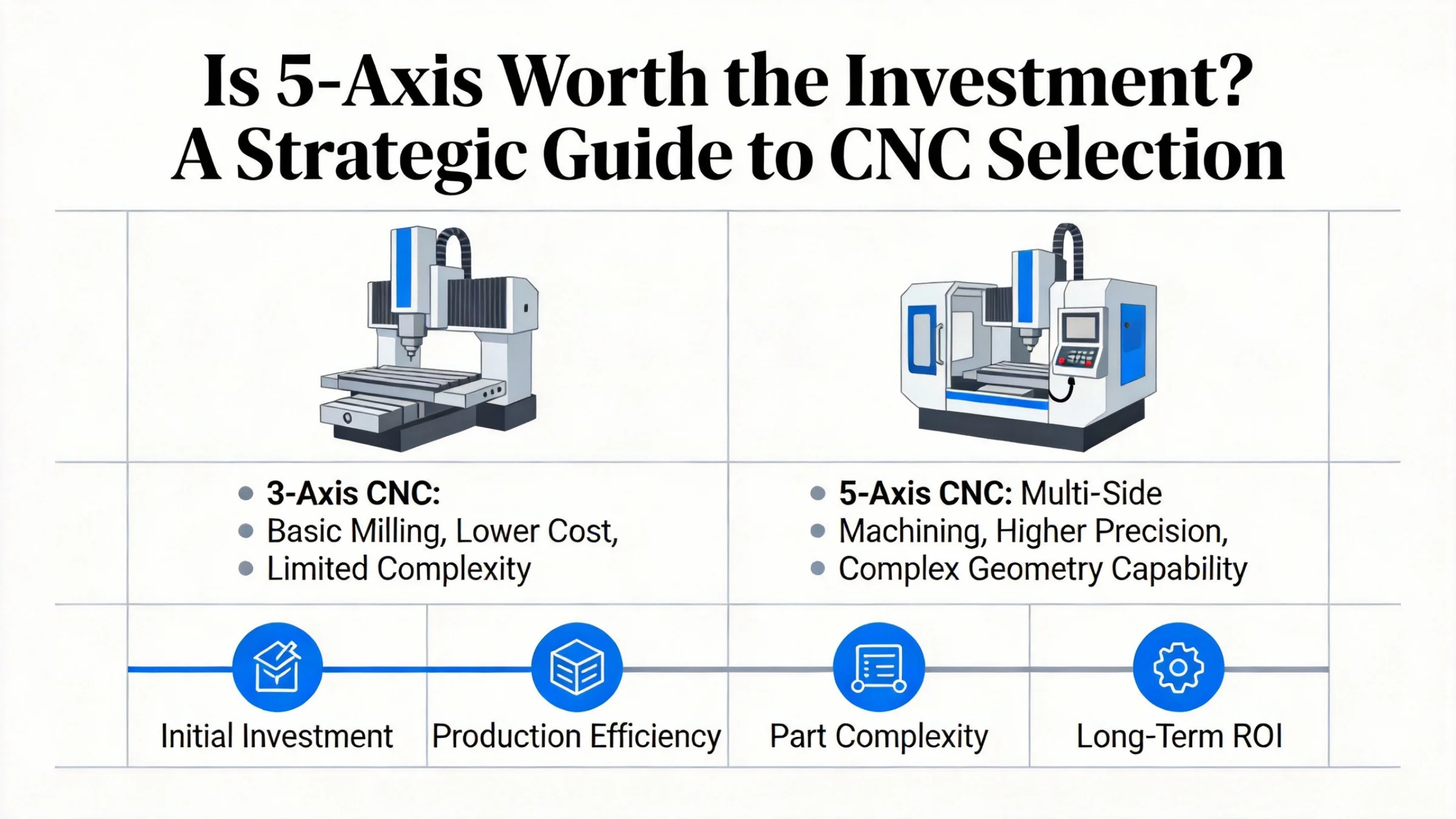
For decades, 3-axis CNC milling has been the reliable backbone of the machine shop. It is the known quantity—predictable, affordable, and effective. However, as modern designs begin to incorporate undercuts, compound angles, and swept surfaces, the 3-axis machine begins to struggle. This is where 5-axis CNC milling enters the conversation, not just as a luxury upgrade, but as a strategic necessity.
At HYM Metal, we see this decision-making process daily. Clients ask us, "Do I really need 5-axis for this part?" or "Why is the setup cost higher if the machine is faster?" To answer these questions, we must look beyond the price tag and understand the fundamental mechanics at play. In this first installment of our comprehensive guide, we will dissect the anatomy of these machines, exploring the kinematics that drive them and the physics that separate a "good" part from a "perfect" one.
2. The Evolution of the Axis
To understand where we are, it helps to understand where we came from. Computer Numerical Control (CNC) machining evolved from the rigid, cam-driven automatic lathes of the mid-20th century. The introduction of the Cartesian coordinate system to machine tools revolutionized metal fabrication by allowing a computer to mathematically define a point in space and drive a cutter to it.
The industry settled on 3-axis CNC milling as the standard because it mirrors the way humans think about space: Left/Right (X), Forward/Backward (Y), and Up/Down (Z). For 90% of manufactured goods—brackets, plates, housings—this logic is sufficient.
However, the 3-axis machine has a critical limitation: it is "blind" to the sides of the part. It can only machine what it can "see" from directly above. To machine the side of a block, a human operator must manually intervene, unclamping the part and rotating it 90 degrees. This manual intervention is the enemy of precision. It introduces what metrologists call "stack-up error." Every time a human touches the part, accuracy degrades.
5-axis machining was born from the need to eliminate this human intervention. By giving the machine the ability to rotate the part or the tool, we empower the computer to "see" every side of the component without interruption.
3. Deep Dive: The Mechanics of Movement
When we talk about axes, we are talking about degrees of freedom. Understanding the specific kinematics of these machines is vital for anyone designing for or purchasing precision machining services.
The 3-Axis Baseline
In a standard Vertical Machining Center (VMC), the spindle is fixed in a vertical orientation.
-
X-Axis: The table moves longitudinally.
-
Y-Axis: The table moves transversely.
-
Z-Axis: The spindle moves vertically.
The cutting tool is always parallel to the Z-axis. This rigidity is excellent for heavy material removal on flat surfaces, known as "hogging out" material. However, it means the tool cannot reach under an overhang or drill a hole at a 45-degree angle without a custom fixture.
The 5-Axis Expansion: A and B (and sometimes C)
A 5-axis machine adds two rotary axes to the standard three linear axes. These are typically defined as:
-
A-Axis: Rotation around the X-axis.
-
B-Axis: Rotation around the Y-axis.
-
C-Axis: Rotation around the Z-axis.
Crucially, a 5-axis machine doesn't just have more motors; it has a fundamentally different architecture. There are two primary configurations used in the industry, and knowing the difference can help you understand which machine is right for your part.
Configuration 1: The Trunnion Table (Table-Table)
In a trunnion setup, the table does the rotating. The milling head remains stationary (like a 3-axis machine), while the table tilts (A-axis) and rotates (C-axis) to present different faces of the workpiece to the spindle.
-
Pros: This design is generally more rigid for smaller parts because the heavy spindle doesn't have to tilt. It offers excellent vibration damping.
-
Cons: The size of the part is limited by the trunnion's swing clearance. If the part is too large, it will hit the machine walls when the table tilts.
-
Best For: Small to medium-sized precision parts like medical implants, small aerospace brackets, and electronic housings.
Configuration 2: The Swivel Head (Head-Head or Head-Table)
In this configuration, the spindle head itself articulates. The table might move in X and Y, but the Z-axis and the tilting action happen at the cutting tool.
-
Pros: It can handle much larger and heavier parts because the workpiece doesn't need to be tilted against gravity. You can machine a massive engine block or an aircraft wing rib on a swivel head machine.
-
Cons: The articulating head can be less rigid than a fixed spindle, potentially limiting heavy roughing cuts on tough materials like Inconel unless the machine is exceptionally high-end.
-
Best For: Large mold dies, aerospace structural components, and heavy metal fabrication.
At HYM Metal, we utilize a mix of these configurations to ensure that whether you have a 1-inch titanium screw or a 20-inch aluminum mold, we have the right kinematics to machine it efficiently.
4. The Physics of the Cut: Why 5-Axis Cuts Better
One of the least understood advantages of 5-axis machining is that it actually produces a better quality cut, even on simple surfaces. This comes down to the physics of rotary tools.
The "Zero Speed" Problem
Imagine a ball-nose end mill—a cutting tool with a rounded tip, often used for sculpting 3D shapes. On a 3-axis machine, when this tool traces a flat surface, the very center tip of the ball is in contact with the part.
Here is the physics problem: The cutting speed (surface footage) of a rotating tool is calculated based on its diameter at the point of contact. At the very tip of a ball nose, the diameter is effectively zero. Therefore, the cutting speed is zero. Instead of shearing the metal, the tool tip is simply rubbing against it.
-
Result: This rubbing generates heat, causes premature tool wear, and leaves a poor surface finish.
The 5-Axis Solution: Tool Tilting
A 5-axis machine solves this by tilting the tool (or the part) slightly—usually by 10 to 15 degrees. By tilting the tool, the contact point moves away from the zero-velocity tip and up to the "cheek" of the ball, where the diameter is larger and the tool is spinning fast.
-
Result: The tool shears the metal cleanly. This results in:
-
Better Surface Finish: Less manual polishing is required.
-
Longer Tool Life: The tool cuts cooler and lasts longer.
-
Faster Cycle Times: We can run the spindle at higher efficiency rates.
-
This capability is known as TCP (Tool Center Point) Control, a sophisticated algorithm inside the machine's controller that adjusts the linear axes in real-time to compensate for the rotary angles, keeping the tool tip exactly where it needs to be while maintaining the optimal cutting angle.
1. Introduction: The Pilot Behind the Machine
In Part 1, we explored the impressive mechanical capabilities of 5-axis machines—their ability to tilt, rotate, and approach a workpiece from any angle. But owning a machine with five axes of movement is like owning a fighter jet; the hardware is useless without a skilled pilot and a sophisticated flight plan. In the world of CNC machining services, that flight plan is the code.
The jump from 3-axis to 5-axis machining represents a massive leap in digital complexity. While the physical cutting of metal remains the same, the mathematics required to control it changes exponentially. For engineers and buyers, understanding this "programming gap" is crucial. It explains why 5-axis CNC milling often carries higher setup costs and why choosing a vendor with proven programming expertise—like HYM Metal—is safer than simply finding the shop with the cheapest machine rate.
In Part 2, we open the "black box" of 5-axis programming. We will look at how programmers avoid catastrophic crashes, the specific cutting strategies that slash cycle times, and the real-world applications where these digital strategies create physical value.
2. The Programming Gap: From Coordinates to Vectors
To appreciate the complexity of 5-axis work, we must contrast it with the standard.
3-Axis Programming (The Cartesian Standard) Programming a 3-axis machine is relatively straightforward. The programmer tells the machine to go to X=10, Y=10, Z=-5. The machine moves there. Because the tool is always vertical, the software (CAM) only needs to calculate the position of the tool tip. It is essentially 2.5D logic applied to a 3D space.
5-Axis Programming (The Vector Challenge) In 5-axis machining, knowing where the tool tip is isn't enough. The machine also needs to know the orientation of the tool. This is defined by a Tool Axis Vector—a mathematical line extending through the center of the tool.
-
The CAM (Computer-Aided Manufacturing) software must calculate the X, Y, and Z position of the tip while simultaneously calculating the A and B rotary angles to keep that vector aligned correctly with the part surface.
-
It must do this thousands of times per second while the machine is moving at high speeds.
This complexity means that 5-axis programming requires a higher caliber of talent. A programmer isn't just plotting points; they are managing spatial relationships, checking for machine limits (will the table rotate too far?), and ensuring the tool holder doesn't collide with the part during a tilt.
3. The High Stakes of Collision Avoidance
In a 3-axis machine, the workspace is open. The spindle is up high, and the part is down low. Crashes are rare and usually due to gross operator error.
In a 5-axis CNC machine, the workspace is crowded. To machine the side of a part, the spindle head must dive deep into the work envelope, often coming within millimeters of the rotary table or the fixture. The risk of collision is exponentially higher. A collision on a high-speed 5-axis machine can cost tens of thousands of dollars in spindle repairs and weeks of downtime.
To mitigate this, HYM Metal utilizes advanced Kinematic Simulation Software.
-
Virtual Twin: Before a single chip is cut, we run the entire program in a virtual environment that contains a perfect digital twin of our specific machines, fixtures, and tools.
-
Collision Checking: The software scans for "near misses" and collisions. It checks if the tool holder will rub against the wall of the part or if the spindle housing will hit the trunnion table during a rotation.
This "digital rehearsal" ensures that when we press the green button on the real machine, the process is safe and reliable. This step is a critical part of the setup cost for 5-axis work, but it is the insurance policy that guarantees your complex parts are delivered on time.
4. Strategic Toolpaths: Swarf vs. Point Milling
5-axis machining isn't just about reaching five sides; it's about how you cut them. Advanced CAM strategies allow us to leverage the side of the tool rather than just the tip, unlocking massive efficiency gains.
Strategy A: Swarf Milling (Flank Milling)
"Swarf" refers to the chips of metal removed during cutting. Swarf milling is a technique where the side (flank) of the cutting tool is used to machine a wall or a bevel.
-
The Concept: Imagine machining a twisted turbine blade. Instead of using the tip of the tool to trace the blade surface in hundreds of tiny passes (like coloring with a fine-point pen), we tilt the tool so the entire side of the cutter lays flat against the blade surface.
-
The Benefit: We can cut the entire height of the blade in one single pass.
-
The Result: This reduces cycle time drastically—often by 80% or more compared to point milling—and produces a perfectly smooth surface finish without "scallop" marks.
-
Best For: Aerospace impellers, twisted fluid channels, and tapered walls.
Strategy B: Point Milling (Surfacing)
For surfaces that curve in two directions simultaneously (like the hood of a car or a hip implant), the side of the tool cannot lie flat. Here, we must use the tip (point) of a ball-nose cutter.
-
The 5-Axis Advantage: As discussed in Part 1, we use 5-axis motion to tilt the tool, maintaining a constant angle relative to the curvature. This keeps the cutting speed optimal and prevents the tool holder from hitting the part.
-
Best For: Molds, dies, and organic anatomical shapes.
5. Real-World Applications: Where Software Meets Steel
How do these programming strategies translate into industry solutions? Here is where precision machining capabilities define product success.
Case Study 1: The Aerospace Impeller (Simultaneous Motion)
An impeller is a centrifugal pump component with curved blades. The space between the blades is tight.
-
The Challenge: A 3-axis tool cannot fit between the blades without gouging the neighboring blade.
-
The 5-Axis Solution: The machine uses simultaneous 5-axis motion to "wiggle" the tool into the gap, tilting it away from the blade on the left, then tilting it back to cut the blade on the right, all while rotating the part to follow the spiral curve. This is the only way to manufacture high-efficiency jet engine compressors.
Case Study 2: Deep Cavity Molds (Reach & Rigidity)
Injection molds for plastic parts often have deep, narrow cavities.
-
The 3-Axis Limitation: To reach the bottom of a 6-inch deep pocket, a 3-axis machine needs a tool sticking out 6+ inches. This long tool is flimsy and vibrates, leaving a rough finish.
-
The 5-Axis Solution: We use a "3+2" strategy. We tilt the tool 30 degrees. Now, the tool holder can enter the cavity, allowing us to use a stubby, rigid 2-inch tool to reach the bottom corner.
-
The Value: The rigid tool cuts faster and leaves a polished finish, reducing the manual labor required for the mold maker.
1. Introduction: The Sticker Shock Trap
In the procurement offices of manufacturing companies worldwide, a familiar scene plays out. A buyer receives two quotes for a complex component.
-
Quote A (3-Axis Shop): Machine Rate: $75/hr.
-
Quote B (5-Axis Shop): Machine Rate: $120/hr.
On the surface, the decision seems obvious. Why pay a 60% premium for the same part? The buyer chooses Quote A, believing they have saved the company money.
Months later, the reality sets in. The project is delayed because of fixture design issues. The first batch has a 10% scrap rate due to misalignment between Operation 2 and Operation 3. The "cheaper" option has ballooned into a budget overrun.
At HYM Metal, we believe transparency is the cure for this inefficiency. While 5-axis CNC milling undeniably commands a higher hourly rate, focusing on that single metric is a strategic error. To understand the true value, we must look at the Total Cost of Production. In Part 3, we will break down the economics of precision machining and prove mathematically how spending more per hour can significantly lower your final invoice.
2. Deconstructing the Hourly Rate
First, let’s address the elephant in the room: Why is 5-axis machining more expensive per hour? It isn't price gouging; it's a reflection of capital and operational intensity.
-
Capital Investment: A high-end 3-axis vertical mill might cost $100,000. A comparable 5-axis machine can easily cost $300,000 to $500,000. The shop must amortize this equipment cost.
-
Skilled Labor: As discussed in Part 2, 5-axis programming and setup require top-tier talent. These machinists and programmers command higher salaries than standard operators.
-
Maintenance & Calibration: Maintaining the volumetric accuracy of five moving axes requires expensive laser calibration and specialized maintenance routines.
So, yes, the ticker is running faster on a 5-axis machine. But the goal of manufacturing isn't to run the machine cheaply; it's to complete the part quickly and correctly.
3. The Hidden Killers of 3-Axis Costs
When you stick to 3-axis CNC milling for complex parts, you invite several "hidden costs" that rarely appear clearly on a quote but always appear on the bottom line.
A. The Fixture Tax
This is the single biggest hidden cost. To machine a part on multiple sides using a 3-axis machine, the part must be held in specific orientations.
-
Scenario: A housing with angled features.
-
3-Axis Reality: You need to design and machine custom "soft jaws" or angled fixture plates to hold the part at 45 degrees.
-
Cost: Designing and machining these fixtures costs money (often $500 - $2,000). You pay for this, either as a line item or buried in the setup cost.
-
5-Axis Reality: The machine simply tilts the part. We use a standard vise or a dovetail holder. Fixture Cost: $0.
B. The WIP (Work in Progress) Bottleneck
In a multi-setup 3-axis process, a batch of 50 parts might sit waiting for Operation 2 while the machine is busy. Parts are moved, cleaned, re-queued, and stored.
-
This ties up cash in inventory.
-
It increases the risk of parts getting damaged during handling.
-
It extends the lead time from days to weeks.
C. The Stack-Up Scrap Rate
Every time a human operator unclamps a part and re-clamps it for the next operation, error is introduced. Even a speck of dust can throw off the alignment by 0.001".
-
If a part requires 6 setups on a 3-axis machine, there are 6 opportunities to scrap the part.
-
If that part is scrapped on the 6th operation, you have lost all the material and labor invested in the previous 5 operations.
-
5-Axis: With "Done-in-One" machining, the part is never moved. The risk of setup-related scrap drops to near zero.
4. The ROI Calculation: A Tale of Two Processes
Let’s put actual numbers to this theory. We will compare the production of 50 complex aluminum manifolds.
The Part: Features on 5 sides, tight tolerance bores.
Option A: Traditional 3-Axis Process
-
Process: 5 separate operations (setups).
-
Fixtures: Requires 3 custom fixtures @ $500 each = $1,500.
-
Setup Time: 1 hour per op x 5 ops = 5 hours total @ $80/hr = $400.
-
Run Time: The sum of all operations is 40 minutes (0.66 hrs) per part.
-
50 parts x 0.66 hrs x $80/hr = $2,640.
-
-
Handling Labor: Operator spends 5 minutes cleaning/loading each part between ops.
-
5 mins x 4 moves x 50 parts = 16.6 hours @ $60/hr = $1,000.
-
-
Total Cost: $1,500 + $400 + $2,640 + $1,000 = $5,540.
-
Unit Cost: $110.80 per part.
Option B: Strategic 5-Axis Process (HYM Metal approach)
-
Process: 2 operations (1 complex op, 1 simple removal op).
-
Fixtures: Standard modular clamping = $0.
-
Setup Time: 2 hours total @ $120/hr = $240.
-
Run Time: 5-axis is efficient, but the rate is higher. Let's assume the same 40 min cycle time (often faster due to rigid tools, but let's be conservative).
-
50 parts x 0.66 hrs x $120/hr = $3,960.
-
-
Handling Labor: Minimal.
-
2 mins x 1 move x 50 parts = 1.6 hours @ $60/hr = $100.
-
-
Total Cost: $0 + $240 + $3,960 + $100 = $4,300.
-
Unit Cost: $86.00 per part.
The Result: Despite the machine rate being 50% higher ($120 vs $80), the 5-axis process is 22% cheaper per part.
Why?
-
We eliminated $1,500 in fixture costs.
-
We eliminated $900 in manual handling labor.
-
We significantly reduced setup time.
This calculation does not even include the value of the shorter lead time (getting the parts a week earlier) or the reduced risk of non-conformance.
5. Tooling Economics: The Bonus Savings
There is a secondary economic benefit often overlooked: Tool Life. As mentioned in Part 1, 5-axis machines allow the use of shorter, stubbier cutting tools because the head can tilt closer to the workpiece.
-
Physics: A shorter tool is stiffer. It vibrates less.
-
Economics: Less vibration means the cutting edge lasts longer.
-
The Saving: In 3-axis machining deep pockets, you might burn through expensive long-reach end mills rapidly due to chatter. In 5-axis, a standard stub end mill might last for the entire batch. This reduces the "consumables" cost on your invoice.
1. Introduction: When Material Dictates Method
In the previous chapters, we analyzed the mechanical motion, the digital programming, and the financial bottom line of CNC machining. But there is one final variable that often acts as the ultimate tie-breaker in the selection process: The Material.
Machining is a violent process. It involves forcing a hard cutter through solid metal to shear it away. The physics of this interaction changes drastically whether you are cutting buttery soft Aluminum 6061 or notoriously tough Inconel 718.
Surprisingly, 5-axis CNC milling offers distinct advantages for both ends of the material spectrum, though for very different reasons. For engineers designing parts for harsh environments, understanding this material-machine relationship is key to ensuring your parts aren't just theoretically possible, but manufacturable at scale.
In this final installment, we will explore why 5-axis is the secret weapon for exotic alloys, review a real-world success story from the HYM Metal floor, and provide our final strategic checklist for your next project.
2. Material Science: The 5-Axis Advantage
Different materials present different enemies to the machinist. 5-axis geometry provides unique weapons to fight them.
A. Aluminum & Magnesium (The Need for Speed)
For soft, non-ferrous metals, the enemy is not tool wear; it is Time. These materials can be cut incredibly fast. The limitation is often how quickly the machine can move.
-
The 5-Axis Edge: Volumetric Removal. Because 5-axis machines can approach the part from the optimal angle, we can maintain higher engagement rates.
-
Complex Roughing: Instead of doing many shallow step-downs (like stairs) on a curved surface, 5-axis allows for Trochoidal Milling on curved paths. This keeps the tool load constant and allows the spindle to scream at maximum RPM, removing cubic inches of material in record time.
B. Titanium & Stainless Steel (The Heat Management)
For tough materials like Titanium (Ti-6Al-4V) or 316 Stainless, the enemy is Heat. Titanium has poor thermal conductivity; it doesn't carry heat away in the chips. The heat stays concentrated at the cutting edge, destroying tools rapidly.
-
The 5-Axis Edge: Interaction Angle. As discussed in Part 1, 5-axis allows us to avoid the "zero surface footage" at the tool tip. By tilting the tool, we engage the cutting edge where it is most efficient.
-
Result: This reduces friction and heat generation. It prevents "work hardening" (where the material becomes harder as you cut it due to heat). A 5-axis toolpath can extend tool life in Titanium by 200-300% compared to a 3-axis path, significantly lowering production costs.
C. Inconel & Superalloys (The Rigidity Challenge)
Inconel is used in jet engines because it retains strength at high temperatures. It is a nightmare to machine. It requires immense rigidity.
-
The 5-Axis Edge: Shorter Tools. We cannot overstate this benefit. To machine a deep flange on a turbine casing in 3-axis, you might need a tool with a 6:1 length-to-diameter ratio. This tool will deflect and chatter in Inconel, likely breaking.
-
The Solution: By tilting the head, HYM Metal can use a stubby 3:1 tool. The increased stiffness allows us to cut this "uncuttable" material with confidence and precision.
3. Case Study: The "Impossible" Manifold
To illustrate the culmination of these factors—mechanics, software, economics, and materials—let’s look at a recent success story from HYM Metal.
The Client: A developer of autonomous underwater vehicles (AUVs). The Part: A hydraulic distribution manifold. The Material: 316 Stainless Steel (for corrosion resistance). The Challenge: The part had complex fluid channels entering from 5 different angles. The previous supplier was using 3-axis machines.
-
Previous Supplier Issues: They required 7 separate setups. Because 316 Stainless work-hardens, the multiple stops and starts led to inconsistent finishes. The cumulative error caused leaks in the high-pressure ports. The scrap rate was 25%.
The HYM Metal Solution: We moved the part to a Simultaneous 5-Axis Machining Center.
-
Setup: We utilized a dovetail fixture to hold the raw block on a tiny tab of material, exposing 5 sides instantly. Setup count reduced from 7 to 2.
-
Strategy: We used a "Swarf Milling" strategy to cut the tapered side walls in a single pass, rather than hundreds of step-downs.
-
Accuracy: By eliminating the re-fixturing, the relative position of the ports was held to within ±0.0005".
The Outcome:
-
Cycle Time: Reduced by 40%.
-
Scrap Rate: Reduced to 0%.
-
Leak Test: 100% pass rate.
-
Cost: Despite the higher machine rate, the final cost per compliant part dropped by 18%.
This is the definition of strategic manufacturing. It wasn't about finding a cheaper shop; it was about finding a smarter process.
4. The Final Verdict: Your Strategic Checklist
We started this guide with a question: Is 5-Axis Worth the Investment?
The answer is yes—but only when applied correctly. It is not a magic wand; it is a precision instrument. As you evaluate your next project, use this final checklist to guide your decision:
Choose 3-Axis CNC Milling If:
-
[ ] The part features are primarily on one or two faces.
-
[ ] The geometry is prismatic (straight lines, flat surfaces).
-
[ ] The quantity is high, and the part is relatively simple.
-
[ ] You are working with a tight budget on a non-critical component.
Choose 5-Axis CNC Milling If:
-
[ ] The part requires machining on 3+ sides (Cost savings via setup reduction).
-
[ ] The design includes complex contours, lofts, or organic shapes.
-
[ ] Tolerance requirements between features on different sides are tight (< 0.002").
-
[ ] The material is difficult (Titanium, Inconel) or deep features require short, rigid tools.
-
[ ] You need the shortest possible lead time and cannot risk setup delays.