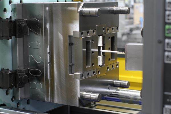
This article provides a comprehensive overview of injection molding design, explaining the key design principles, molding process, material selection, mold lifespan, common defects, and practical considerations for producing high-quality plastic parts efficiently and cost-effectively.
What is injection molding design?
Injection molding design refers to the process of designing plastic parts, molds, and manufacturing features specifically for the injection molding process. Unlike general product design, injection molding design must consider how molten plastic flows into a mold, cools, shrinks, and is eventually ejected from the mold.
Injection molding is widely used to manufacture plastic components for industries such as automotive, electronics, medical devices, consumer products, packaging, appliances, and industrial equipment. The process is suitable for producing both simple and highly detailed components in large quantities.
A successful injection molding design balances functionality, manufacturability, appearance, material selection, tooling cost, and production efficiency. A part may look good in a CAD model but still be difficult or expensive to manufacture if it has insufficient draft angles, inconsistent wall thickness, deep undercuts, or other features that complicate mold construction.
Good design practices should therefore be considered early in product development rather than after the mold has already been manufactured. Early design optimization can reduce tooling modifications, shorten production cycles, improve part quality, and lower overall manufacturing costs.
How to design for injection molding?
Designing a part for injection molding requires an understanding of both the plastic material and the mold-making process. The goal is to create a geometry that can be filled, cooled, and ejected reliably while meeting the functional requirements of the final product.
Here are some important injection molding design guidelines:
- Maintain consistent wall thickness. Avoid large variations in wall thickness whenever possible. Consistent walls help molten plastic cool more uniformly and reduce defects such as sink marks, warpage, and internal stresses.
- Add draft angles. Draft allows the molded part to be removed from the mold more easily. A small draft angle is commonly added to vertical surfaces, although the appropriate angle depends on the material, surface texture, depth, and mold design.
- Use ribs instead of excessively thick walls. When additional stiffness is required, ribs can provide structural support without creating thick sections that may produce sink marks or extended cooling times.
- Design suitable bosses. Bosses are frequently used for screws, inserts, and assembly features. Their wall thickness should be controlled to reduce the risk of sink marks and other molding defects.
- Consider parting lines. The location of the mold parting line affects appearance, tooling complexity, and the ability to eject the part. A good parting-line strategy can simplify mold construction and reduce tooling costs.
- Minimize unnecessary undercuts. Undercuts may require slides, lifters, collapsible cores, or other mechanisms, increasing mold complexity and cost.
- Plan the gate location. Gate position affects filling behavior, weld lines, air entrapment, cosmetic appearance, and dimensional stability. The gate should be positioned according to the part geometry and material flow requirements.
- Consider shrinkage. Plastic materials shrink as they cool. Mold dimensions must account for the expected shrinkage of the selected material.
The best approach is to involve mold designers and injection molding engineers during the product design stage. Design-for-manufacturing reviews can identify potential problems before tooling begins.
What are the four stages of injection molding?
The injection molding process can be broadly divided into four main stages: clamping, injection, cooling, and ejection. These stages work together to transform plastic pellets into finished molded components.
- Clamping: The two halves of the injection mold are closed and held together under sufficient clamping force. The mold must remain securely closed during injection to prevent molten plastic from forcing the mold halves apart.
- Injection: Plastic pellets are melted inside the injection unit and pushed forward by a screw. The molten plastic is injected through the nozzle and runner system into the mold cavity.
- Cooling: After the cavity is filled, the plastic begins to cool and solidify. Cooling channels inside the mold circulate a coolant to remove heat and help control the cooling rate.
- Ejection: Once the molded part has cooled sufficiently, the mold opens and an ejector system pushes the part out of the cavity. The mold then closes and the next molding cycle begins.
In actual production, these stages overlap in terms of machine operation and process control. Cycle time is influenced by injection speed, packing pressure, cooling time, material properties, mold temperature, part thickness, and other factors.
How thick can your injection mold be?
There is no single maximum wall thickness for injection molded plastic parts because the practical limit depends on the material, part geometry, mold design, cooling system, and required quality. However, thinner and more consistent walls are generally preferred for conventional injection molding.
Many general-purpose injection molded parts use wall thicknesses in the approximate range of 1 to 4 mm, although thinner or thicker sections are possible for specific applications. Engineering materials, structural components, and specialized molding processes may use different thicknesses.
Very thick sections can cause several problems:
- Longer cooling times: Thick plastic sections require more time for heat to escape from the part.
- Sink marks: Thick areas can shrink internally as they cool, creating visible depressions on the surface.
- Voids: Internal cavities can form when the outer surface solidifies before the inside has cooled sufficiently.
- Warpage: Uneven cooling and shrinkage can cause the finished component to deform.
- Higher material consumption: Excessively thick parts require more resin and can increase production costs.
If a part requires greater strength, increasing wall thickness is not always the best solution. Engineers can often improve stiffness by adding ribs, gussets, curved sections, or other structural features while keeping the basic wall thickness relatively consistent.
How long does an injection mold last?
The service life of an injection mold depends heavily on the mold material, construction quality, plastic resin, production conditions, maintenance schedule, and required production volume. A mold designed for a few thousand parts may have very different specifications from a production mold intended to manufacture millions of components.
In general, injection molds can be designed for production volumes ranging from thousands to millions of cycles. Tool steels are commonly selected for high-volume applications because they provide good wear resistance and durability. Aluminum molds may be suitable for prototypes, development work, and lower-volume production but typically have a shorter service life under demanding conditions.
Several factors affect mold lifespan:
- Type and hardness of mold steel
- Abrasiveness of the plastic material
- Mold temperature and injection pressure
- Cycle time and production frequency
- Quality of mold machining and heat treatment
- Lubrication and preventive maintenance
- Corrosive or moisture-sensitive materials
Proper maintenance can significantly extend mold life. Regular cleaning, lubrication, inspection of moving components, and maintenance of cooling channels can help prevent premature wear and unexpected production downtime.
Which material is best for injection molding?
There is no single material that is best for every injection molding application. The most appropriate material depends on the required strength, stiffness, impact resistance, chemical resistance, temperature resistance, appearance, cost, and regulatory requirements.
| Material | Key Characteristics | Common Applications |
|---|---|---|
| ABS | Good impact resistance, dimensional stability, and surface appearance | Housings, consumer products, automotive components |
| PP | Lightweight, good chemical resistance, fatigue resistance, and relatively low cost | Containers, automotive parts, hinges, household products |
| PE | Good chemical resistance, toughness, and moisture resistance | Packaging, containers, pipes, consumer products |
| PC | High impact strength, transparency options, and good heat resistance | Electronic housings, lenses, safety components |
| PA (Nylon) | High strength, wear resistance, and good mechanical performance | Gears, bushings, automotive and industrial components |
| POM | Low friction, stiffness, dimensional stability, and wear resistance | Gears, precision components, mechanical assemblies |
| TPU | Flexible, elastic, and abrasion resistant | Seals, grips, protective parts, flexible components |
Material selection should also consider additives and reinforcement. Glass fiber, mineral fillers, flame retardants, UV stabilizers, and other additives can significantly change the processing and performance characteristics of a resin.
For example, glass-filled nylon can provide higher stiffness and strength but may also increase mold wear and affect part shrinkage. A material should therefore be selected based on both final product requirements and injection molding behavior.
What are common injection molding defects?
Injection molding defects can result from improper part design, unsuitable materials, incorrect processing parameters, inadequate mold design, or equipment problems. Identifying the cause is important because simply changing one machine parameter may not solve a defect caused by the underlying part or mold design.
| Injection Molding Defect | Common Causes | Possible Solutions |
|---|---|---|
| Sink Marks | Excessive wall thickness, thick ribs or bosses, and insufficient packing. | Reduce excessive thickness, optimize packing pressure, and improve cooling. |
| Warpage | Uneven cooling, inconsistent wall thickness, material orientation, or unbalanced shrinkage. | Improve cooling balance, maintain more uniform walls, and optimize processing conditions. |
| Short Shots | Insufficient injection pressure, inadequate melt temperature, restricted flow, or poor venting. | Optimize injection pressure and temperature, improve flow paths, and add or improve vents. |
| Flash | Excessive injection pressure, insufficient clamping force, mold wear, or poor mold alignment. | Optimize pressure and clamping force and inspect the mold for wear or alignment problems. |
| Weld Lines | Two or more plastic flow fronts meeting during cavity filling. | Optimize gate location, flow path, mold temperature, and injection conditions. |
| Burn Marks | Trapped air or gas becoming compressed and overheated during filling. | Improve mold venting and optimize injection speed and process conditions. |
| Flow Marks | Variations in material flow, injection speed, or cooling. | Optimize injection speed, mold temperature, gate design, and material flow. |
How does wall thickness affect injection molding?
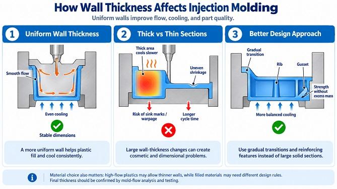
Wall thickness is one of the most important considerations in injection molding design because it affects material flow, cooling time, shrinkage, mechanical strength, and cycle time.
When a part has significant changes in wall thickness, thicker areas generally remain molten longer than thinner sections. This difference can produce uneven shrinkage and dimensional variation. A more uniform design allows the mold cooling system to remove heat more consistently.
When thickness transitions are necessary, designers can use gradual transitions rather than abrupt changes. Ribs and gussets can also be used to reinforce thin walls without creating large solid sections.
The selected plastic material also influences the ideal wall thickness. Materials with higher flowability may be suitable for thinner sections, while highly filled or reinforced materials may require different design considerations. The final thickness should therefore be validated through mold-flow analysis and practical testing when dimensional or cosmetic requirements are demanding.
What is draft angle in injection molding?
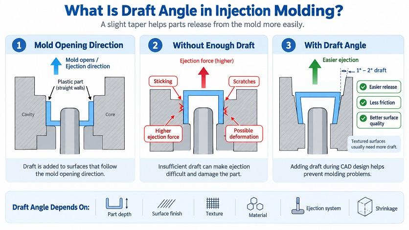
A draft angle is a slight taper applied to surfaces that are parallel or nearly parallel to the direction in which the mold opens. Draft helps the molded component separate from the mold cavity and core during ejection.
Without sufficient draft, the part may stick to the mold, become scratched, deform during ejection, or require excessive ejection force. Textured surfaces usually need more draft because the texture increases the contact area between the part and the mold.
The required draft depends on several factors, including:
- Part depth
- Mold surface finish
- Texture or engraving
- Plastic material
- Ejection system
- Shrinkage characteristics
Adding draft during the initial CAD design stage is generally much easier than modifying a finished mold. Designers should therefore identify the mold opening direction and draft requirements before finalizing the part geometry.
How do ribs and bosses affect injection molded parts?
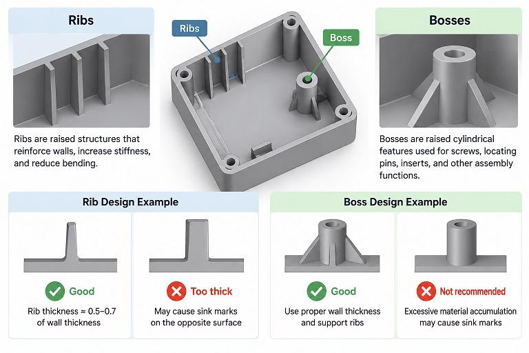
Ribs and bosses are common structural features in injection molded parts. They allow designers to increase stiffness, support fasteners, and improve assembly without making the entire component unnecessarily thick.
Ribs are raised structures that reinforce walls and reduce bending. They are commonly used in housings, brackets, covers, and structural components. However, ribs that are too thick can create sink marks or other cosmetic problems on the opposite surface.
Bosses are typically cylindrical or similar raised features used for screws, locating pins, inserts, and other assembly functions. Bosses should be designed with appropriate wall thickness and support features to avoid excessive material accumulation.
When ribs and bosses are connected, a balanced geometry can improve structural performance while minimizing thick plastic sections. The exact dimensions depend on the resin, load requirements, cosmetic expectations, and manufacturing process.
How do you reduce injection molding costs?
Injection molding can be highly cost-effective for high-volume production, but tooling and part design decisions can have a significant impact on total manufacturing cost. Cost reduction should therefore begin before the mold is manufactured.
Here are several ways to reduce injection molding costs:
- Simplify the part geometry. Avoid unnecessary undercuts, complex moving mechanisms, and difficult-to-machine features when they do not provide meaningful product benefits.
- Choose an appropriate material. A lower-cost resin may be sufficient when the application does not require premium mechanical, thermal, or chemical performance.
- Optimize wall thickness. Reducing unnecessary material can lower resin consumption and shorten cooling time.
- Design for standard tooling components. Standard mold components can reduce machining time, tooling complexity, and replacement costs.
- Plan production volume carefully. A high-volume production part may justify a more durable and complex mold, while a low-volume application may benefit from simpler tooling.
- Perform design validation early. Identifying problems before mold construction is usually less expensive than modifying a completed mold.
The lowest tooling cost is not always the lowest overall manufacturing cost. A more durable mold may have a higher initial price but provide better reliability and lower maintenance costs over millions of cycles.
What should you consider when designing an injection mold?
Injection mold design must account for the geometry of the part, selected material, expected production volume, cycle time, cosmetic requirements, and molding machine capabilities.
Important mold design considerations include:
- Parting line: Determines how the mold separates and can affect part appearance and ejection.
- Gate design: Controls where molten plastic enters the cavity and influences filling behavior.
- Runner system: Delivers molten material from the injection unit to one or more cavities.
- Cooling system: Removes heat from the mold and has a major effect on cycle time and dimensional stability.
- Venting: Allows trapped air and gases to escape from the cavity during filling.
- Ejection system: Removes the finished part from the mold while minimizing deformation and surface damage.
- Slides and lifters: Allow certain undercut features to be molded and released.
For complex components, mold-flow simulation can be used to evaluate filling, packing, cooling, shrinkage, weld lines, and potential warpage before manufacturing the tool. This can help engineers optimize gate locations, cooling layouts, and part geometry.
What is the typical injection molding cycle time?
Injection molding cycle time varies widely depending on part size, wall thickness, material, mold temperature, cooling efficiency, machine settings, and the complexity of the mold. A small thin-walled component may have a cycle of only a few seconds, while a larger or thicker component can require significantly longer.
Cooling often represents a substantial portion of the total cycle because the part must become sufficiently rigid before it can be ejected. Reducing unnecessary wall thickness and improving the mold cooling system can therefore increase production efficiency.
A typical production cycle includes mold closing, injection, packing or holding, cooling, mold opening, and ejection. Some operations may overlap, and modern injection molding machines are designed to optimize these steps for shorter cycle times.
However, the fastest possible cycle is not necessarily the best cycle. Excessively short cooling or filling times can cause dimensional instability, warpage, residual stress, or other defects. The ideal cycle balances quality, productivity, energy consumption, and equipment capability.
How can you improve injection molded part quality?
Improving injection molded part quality requires coordination between product design, mold design, material selection, machine settings, and quality control. Problems should be addressed systematically rather than relying only on trial-and-error adjustments to processing parameters.
A practical quality improvement process includes:
- Review the part design: Check wall thickness, draft, ribs, bosses, radii, undercuts, and other features that may affect manufacturability.
- Confirm the material: Verify that the selected resin meets the required mechanical, thermal, chemical, and appearance requirements.
- Optimize the mold: Evaluate gates, runners, cooling channels, vents, parting lines, and ejection mechanisms.
- Set appropriate processing conditions: Injection speed, pressure, holding pressure, mold temperature, melt temperature, and cooling time should be optimized for the specific material and part.
- Inspect the first molded samples: Check dimensions, appearance, assembly, and functional performance.
- Monitor production: Consistent process monitoring helps identify drift before it creates large quantities of defective parts.
For high-volume or precision applications, statistical process control and automated inspection can further improve consistency. Preventive mold maintenance is also important because worn components, blocked cooling channels, and damaged cavity surfaces can gradually affect product quality.
Conclusion
Injection molding design is an important part of developing reliable, cost-effective plastic products. A successful design must consider more than the appearance and function of the final component. Wall thickness, draft angles, ribs, bosses, parting lines, gate locations, material properties, cooling, ejection, and mold lifespan all influence the final result.
When designing for injection molding, it is generally best to maintain consistent wall thickness, use suitable draft angles, avoid unnecessary undercuts, and use ribs or other structural features instead of excessively thick sections. Selecting the right plastic material is equally important because different resins offer different combinations of strength, flexibility, chemical resistance, heat resistance, appearance, and cost.
Common injection molding defects such as sink marks, warpage, short shots, flash, weld lines, burn marks, and flow marks can often be reduced through better part design, mold design, material selection, and process optimization.
Ultimately, the best injection molding design is one that considers product performance, manufacturability, tooling cost, production volume, cycle time, and long-term reliability together. Involving injection molding engineers and mold designers early in the product development process can help identify potential problems before tooling begins, resulting in a more efficient manufacturing process and a higher-quality finished product.