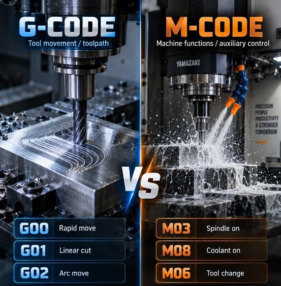
This article explains the differences between G-code and M-code in CNC programming, covering their functions, common commands, and applications in milling machines and lathes. It provides practical examples of frequently used codes, including G20, G50, G53, G70, G90, M05, M06, and M30, while highlighting variations across FANUC, Haas, Okuma, and other CNC controllers. The article also introduces related CNC address codes such as F, S, T, and X/Y/Z, helping readers understand how different codes work together in CNC programming.
What is G-code in CNC?
G-code is a programming language used to control the movement and machining functions of a CNC machine. The letter G generally identifies commands that control geometric or preparatory functions, such as tool movement, coordinate systems, cutting modes, and machining cycles. G-code tells the CNC machine how and where the cutting tool should move to produce a particular part.
A G-code program normally contains a series of commands, coordinates, feed rates, spindle speeds, and other instructions. For example, a command such as G00 X50 Y20 tells a CNC machine to move rapidly to the specified X and Y coordinates without performing a cutting operation. A command such as G01 X50 Y20 F100 instructs the machine to move in a controlled linear cutting motion at a specified feed rate.
G-code is widely used on CNC milling machines, CNC lathes, machining centers, routers, and other automated machine tools. Although many controllers support the same basic G-code standards, the exact meaning and available commands can vary between controller manufacturers.
For this reason, a G-code program written for one CNC controller should always be checked against the machine's programming manual before it is run. FANUC, Okuma, Siemens, Haas, and other CNC control systems can have different commands, options, and parameter settings.
What is M-code in CNC?
M-code is another group of commands used in CNC programming. While G-code primarily controls tool movement and machining modes, M-code controls auxiliary machine functions. These functions can include starting and stopping the spindle, changing tools, turning coolant on or off, stopping the program, and activating other machine-specific functions.
The letter M in M-code is commonly associated with miscellaneous or machine functions. Unlike a G-code that typically describes the geometry or motion of machining, an M-code tells the CNC control to perform an auxiliary operation.
Common examples include M03 for clockwise spindle rotation, M04 for counterclockwise spindle rotation, M05 for stopping the spindle, M06 for a tool change, and M30 for ending and resetting a CNC program.
M-codes are highly dependent on the CNC controller and machine builder. An M-code that performs a particular function on one machine may perform a different function on another machine. Therefore, operators should verify M-code assignments in the documentation for their specific CNC machine.
G-code vs M-code
The main difference between G-code and M-code is their purpose. G-codes primarily control machining geometry, movement, and operating modes, while M-codes primarily control auxiliary machine functions.
For example, G00 and G01 control how the tool moves, while M03 and M05 control the spindle. G20 changes the programming units to inches on controllers that support this convention, while M08 commonly turns coolant on.
G-code and M-code normally work together in a CNC program. A machining operation may use G-codes to position and move the tool while M-codes control the spindle, coolant, tool changer, and other machine functions.
Here are the main differences between G-code and M-code.
| Feature | G-code | M-code |
|---|---|---|
| Main purpose | Controls tool movement, machining modes, coordinates, and cycles | Controls auxiliary and machine-specific functions |
| Letter | G | M |
| Typical functions | Rapid movement, linear cutting, circular interpolation, coordinate systems, canned cycles | Spindle control, coolant, tool changes, program stop, program end |
| Examples | G00, G01, G02, G03, G20, G53, G80, G90 | M03, M04, M05, M06, M07, M08, M30 |
| Machine dependence | Basic commands are often standardized, but many functions are controller-specific | Often highly dependent on the controller and machine builder |
| Main role | Defines how machining takes place | Controls supporting machine operations |
How do G-code and M-code work together?
G-code and M-code are normally combined to create a complete CNC machining program. A CNC controller reads the program block by block and interprets commands to determine tool movement, spindle operation, coolant operation, coordinate systems, feed rates, and other machine functions.
A simple machining sequence might begin by selecting a coordinate system and measurement unit, followed by a tool change and spindle start. The machine then moves the tool to the required position using G-code. During cutting, additional G-codes define the tool path, while M-codes can control coolant or other auxiliary functions.
For example, a simplified milling program could contain commands such as:
G20              ; Use inches
G90              ; Use absolute positioning
G00 X0 Y0        ; Rapid move to X0, Y0
M03 S2000        ; Start spindle clockwise at 2000 RPM
G01 X50 F100     ; Cut to X50 at feed rate 100
M05              ; Stop spindle
M30              ; End program
In this simplified example, G20 selects inch programming on controllers that use G20 for inch units, G90 selects absolute positioning, G00 performs rapid positioning, M03 starts the spindle clockwise, G01 commands linear interpolation, M05 stops the spindle, and M30 ends the program. The exact behavior can depend on the CNC controller.
Real production programs are usually much more detailed. They may contain tool offsets, work offsets, cutter compensation, drilling cycles, spindle speed commands, coolant commands, safety moves, and multiple machining operations.
Common G-codes
There are many G-codes used in CNC machining, and their functions can vary by controller and machine type. The following table lists some of the most common G-codes used on CNC mills, lathes, and machining centers.
| G-code | Common function | Application | Notes |
|---|---|---|---|
| G00 | Rapid positioning | Milling & Lathe | — |
| G01 | Linear interpolation | Milling & Lathe | — |
| G02 | Clockwise circular interpolation | Milling & Lathe | — |
| G03 | Counterclockwise circular interpolation | Milling & Lathe | — |
| G04 | Dwell | Milling & Lathe | — |
| G17 | Select XY plane | Mainly Milling | Lathe commonly uses G18 |
| G20 | Inch programming | Milling & Lathe | — |
| G21 | Metric programming | Milling & Lathe | — |
| G40 | Cancel cutter/tool-nose compensation | Milling & Lathe | Function varies by application |
| G41 | Cutter/tool-nose compensation left | Milling & Lathe | Function varies by application |
| G42 | Cutter/tool-nose compensation right | Milling & Lathe | Function varies by application |
| G43 | Tool length compensation | Mainly Milling | Common on machining centers |
| G53 | Machine coordinate positioning | Milling & Lathe | Controller- and machine-dependent |
| G54-G59 | Work coordinate system selection | Milling & Lathe | Availability may vary by controller |
| G90 | Absolute programming | Milling & Lathe | Function may differ on some lathe controls |
| G91 | Incremental programming | Milling & Lathe | — |
This G-code list is a general reference rather than a universal standard. Some codes have different meanings depending on whether the machine is a lathe, mill, router, or another type of CNC equipment.
Many of these G-codes are used on major CNC control systems, including FANUC, Haas, Siemens, and Okuma. However, code availability, functions, and syntax can vary by controller and machine configuration.
G20 – Inch Programming
G20 is commonly used to select inch programming on CNC controls that follow this convention. Its counterpart is usually G21, which selects metric programming.
For example:
G20              ; Use inches
G90              ; Use absolute positioning
G01 X2.000 Y1.000 F10  ; Linear move to X2.000, Y1.000 at feed rate 10
In this example, the coordinates are interpreted using inch units if the controller supports G20 in the conventional manner. A metric program may instead use:
G21                    ; Use millimeters
G90                    ; Use absolute positioning
G01 X50.000 Y25.000 F250 ; Linear move to X50.000, Y25.000 at feed rate 250
Switching between G20 and G21 without checking the programmed dimensions can cause serious machining errors. Operators should confirm the active unit system before running a program, especially when importing programs from CAM software.
G53 – Machine Coordinate System Positioning
G53 is commonly used on FANUC-style CNC controls to specify positioning in the machine coordinate system for a programmed motion block. Unlike a work coordinate system such as G54, machine coordinates are based on the machine's reference system.
A typical use is to move a tool to a machine-coordinate position for a safe tool-change or clearance location, depending on the machine configuration. For example:
G53 G00 Z0
On a compatible control, this command can command a rapid move in the machine coordinate system. The exact syntax and behavior should always be confirmed for the specific machine because G53 implementation and machine-coordinate conventions can vary.
G53 is particularly useful when a programmer needs a machine-reference movement rather than a movement relative to the active work offset. It is important not to assume that a G53 command is automatically safe; the programmer must understand the machine's travel limits, tool length, fixture position, and clearance.
G50 – Spindle Speed Limiting
G50 is a controller-dependent code and its meaning can differ significantly between CNC milling and turning applications. On many CNC lathes, G50 is associated with spindle speed limitation or coordinate-setting functions depending on the control configuration.
For example, on many FANUC-type CNC lathes, G50 can be used to establish a maximum spindle speed when constant surface speed is being used. This can prevent the spindle from exceeding a programmed limit as the tool approaches the center of a rotating workpiece.
Because G50 has different applications across CNC systems, programmers should never treat it as a universal command. The controller manual should be checked before using G50 in a production program.
G70 – Finishing Cycle
G70 is commonly associated with a finishing cycle on FANUC-style CNC lathes. It can be used after roughing cycles such as G71, G72, or G73 to perform a finishing pass along a previously defined profile.
A simplified turning sequence may look like:
G71 ...
...
G70 ...
In this type of application, the roughing cycle removes most of the material and the finishing cycle follows the programmed profile to achieve the final dimensions and surface finish.
The exact format of G70 and the associated block structure depends on the CNC controller. Before using a G70 cycle, the programmer should verify the required parameters and relationship with the roughing cycle on the specific lathe.
G90 – Absolute Programming
G90 commonly selects absolute programming, meaning that programmed coordinates are interpreted relative to the active work coordinate system rather than relative to the tool's current position. However, the exact behavior of G90 can differ between CNC controls and machine types.
On a CNC lathe, programmers must pay particular attention to the controller's interpretation of G90 because some lathe controls use certain G-code numbers for machining cycles or functions that differ from milling applications.
For this reason, G90 should not be assumed to have the same meaning on every CNC machine. The machine's programming manual should be used to verify the command before creating or modifying a production program.
G-code Example
G-code examples are useful for understanding how individual commands work together. A simple example for a CNC milling machine is shown below:
%
O1001
G20 G90          ; Use inches and absolute positioning
G54              ; Select work coordinate system G54
G00 X0 Y0        ; Rapid move to X0, Y0
M03 S2000        ; Start spindle clockwise at 2000 RPM
G00 Z0.1         ; Rapid move to Z0.1
G01 Z-0.05 F20   ; Cut down to Z-0.05 at feed rate 20
G01 X2.0 F10     ; Cut to X2.0 at feed rate 10
G01 Y1.0         ; Cut to Y1.0
G01 X0           ; Cut back to X0
G01 Y0            ; Cut back to Y0
G00 Z0.5         ; Rapid move up to Z0.5
M05              ; Stop spindle
M30              ; End program
%
This example illustrates a basic rectangular tool path. G20 selects inch units on compatible controls, G90 selects absolute positioning, and G54 selects a work coordinate system. G00 is used for rapid positioning, while G01 creates controlled linear movements. M03 starts the spindle and M05 stops it.
The values in this example are only for illustration. A CNC program should not be copied directly to a machine without checking the controller syntax, tool offsets, workpiece location, tooling, spindle speed, feed rate, clearance, and machine-specific safety requirements.
CNC programmers commonly use simulation or dry-run procedures to verify a program before cutting a workpiece. This is particularly important when a program has been generated by CAM software or transferred from another CNC controller.
Common M-codes
The following are common M-codes used on many CNC machines. Exact functions and availability may vary by machine and CNC controller.
| M-code | Common function | Application | Notes |
|---|---|---|---|
| M00 | Program stop | Milling & Lathe | — |
| M01 | Optional program stop | Milling & Lathe | |
| M02 | Program end | Milling & Lathe | Function may vary by controller |
| M03 | Spindle clockwise rotation | Milling & Lathe | — |
| M04 | Spindle counterclockwise rotation | Milling & Lathe | — |
| M05 | Spindle stop | Milling & Lathe | — |
| M06 | Tool change | Mainly Milling | Availability depends on machine configuration |
| M07 | Auxiliary coolant or mist on | Milling & Lathe | Function varies by machine |
| M08 | Coolant on | Milling & Lathe | — |
| M09 | Coolant off | Milling & Lathe | — |
| M19 | Spindle orientation | Mainly Milling | Availability depends on machine configuration |
| M30 | Program end and reset | Milling & Lathe | Reset behavior may vary by controller |
This table provides a general reference for commonly used M-codes. Individual CNC machines may assign additional M-codes to functions such as hydraulic clamping, pallet changes, chip conveyors, door control, probing, or other machine-specific equipment.
M5 – Spindle Stop
M5, often written as M05, is commonly used to stop the spindle. If the spindle is rotating because of an earlier M03 or M04 command, M05 tells the CNC control to stop spindle rotation.
A simple example is:
M03 S1500       ; Start spindle clockwise at 1500 RPM
G01 X50 F100     ; Linear move to X50 at feed rate 100
M05              ; Stop spindle
In this sequence, the spindle is started clockwise at the programmed speed, the tool performs a linear movement, and M05 stops the spindle. The machine may require additional commands before another operation, depending on the machining process.
M6 – Tool Change
M06, often written as M6, is commonly used to command an automatic tool change on CNC machines equipped with a tool changer. It is normally used together with a tool-selection command such as T1, T2, or another tool number.
A simplified example is:
T01 M06
This tells a compatible CNC control to select and change to the specified tool. The exact sequence can vary depending on the controller and machine builder. Some machines may require the tool to be positioned at a specific location or may execute additional machine-specific operations automatically.
Tool changes should be performed only when sufficient clearance is available. The programmer should also verify that the correct tool length and diameter offsets are active before cutting begins.
M7 – Mist Coolant On
M07, commonly written as M7, is generally used for an auxiliary coolant function on many CNC controls. Depending on the machine, this may activate mist coolant or another coolant-related output.
A typical sequence may include:
M07              ; Turn on mist coolant
G01 X50 F100     ; Linear move to X50 at feed rate 100
M09              ; Turn off coolant
Here, M07 activates the assigned coolant or auxiliary function, while M09 commonly turns coolant functions off. However, the exact coolant arrangement varies between machines. Some CNC machines may use M07 for mist, M08 for flood coolant, or assign different functions to these codes.
M30 – Program End and Reset
M30 is commonly used to indicate the end of a CNC program and reset the program to its beginning on many controllers. It is one of the most frequently encountered M-codes in CNC programs.
A typical program ending may look like:
M05              ; Stop spindle
M09              ; Turn off coolant
G00 Z0            ; Rapid move to Z0
M30              ; End program and reset
The commands before M30 can stop the spindle, turn off coolant, and move the tool to an appropriate position. M30 then ends the program according to the controller's programmed behavior.
The exact reset behavior may vary between CNC controls. Operators should verify the controller manual if a program requires a specific end-of-program sequence.
M-code Example
M-code examples can be understood by looking at the auxiliary functions they control. For example, M03 starts clockwise spindle rotation, M04 starts counterclockwise spindle rotation, and M05 stops the spindle. M06 commonly commands a tool change, while M08 and M09 commonly control coolant.
A simple sequence might be:
T01 M06          ; Select tool 1 and perform tool change
M03 S1800        ; Start spindle clockwise at 1800 RPM
M08              ; Turn on flood coolant
G01 X50 F100     ; Linear move to X50 at feed rate 100
M09              ; Turn off coolant
M05              ; Stop spindle
M30              ; End program and reset
In general terms, this sequence selects a tool, starts the spindle, turns on coolant, performs a programmed movement, turns off coolant, stops the spindle, and ends the program.
This is only a simplified educational example. Actual machine programs often require additional safety moves, work offsets, tool compensation, spindle limits, and controller-specific commands.
G-code and M-code example for CNC lathes
CNC lathes use G-code and M-code to control turning operations such as facing, rough turning, finishing, threading, drilling, grooving, and parting. The basic programming concepts are similar to those used on milling machines, but the coordinate system and machining cycles are different.
Common lathe G-codes can include rapid positioning, linear interpolation, circular interpolation, work coordinate functions, tool compensation, threading cycles, roughing cycles, and finishing cycles.
For example, G70 is commonly associated with a finishing cycle on FANUC-style lathes, while G71 is commonly used for a rough turning cycle. Other codes may be used for threading, grooving, drilling, or canned operations.
A simplified CNC lathe sequence might look like:
G21 G90          ; Use millimeters and absolute positioning
T0101            ; Select tool 1 with offset 1
G50 S2500        ; Set maximum spindle speed to 2500 RPM
G96 S180 M03     ; Set constant surface speed to 180 and start spindle clockwise
G00 X50 Z2       ; Rapid move to X50, Z2
G01 Z0 F0.2      ; Linear move to Z0 at feed rate 0.2
G00 X100 Z100    ; Rapid move to X100, Z100
M05              ; Stop spindle
M30              ; End program and reset
This example demonstrates the general relationship between G-code and M-code rather than providing a machine-ready production program. Commands such as G50, G96, tool offsets, spindle speed, and feed rate must be checked against the specific lathe controller and tooling setup.
Other CNC Program Codes: F, S, T, and More
In addition to G-codes and M-codes, CNC programs use other address codes to define machining parameters, tool information, and coordinate values. These codes work together with G-codes and M-codes to control the machining process accurately and efficiently.
| Code | Meaning | Function | Application | Example |
|---|---|---|---|---|
| F | Feed Rate | Specifies the speed at which the cutting tool moves during machining. | Milling & Lathe |
G01 X50 F200 – Linear movement with a feed rate of 200
|
| S | Spindle Speed | Sets the spindle rotation speed, usually in revolutions per minute (RPM). | Milling & Lathe |
S1500 – Set spindle speed to 1500 RPM
|
| T | Tool Selection | Specifies the tool to be selected for the machining operation. | Milling & Lathe |
T01 – Select tool number 1
|
| N | Sequence Number | Identifies individual program blocks or lines and can be used for program organization and reference. | Milling & Lathe |
N100 G01 X50 F200
|
| X, Y, Z | Axis Coordinates | Define the position or movement of the cutting tool along the machine axes. | Milling & Lathe |
G00 X100 Y50 Z5 – Rapid move to the specified coordinates
|
| I, J, K | Arc Center Coordinates | Define the arc center relative to the starting point when programming circular interpolation. | Mainly Milling |
G02 X50 Y20 I10 J0 – Clockwise arc with center offset
|
| R | Radius / R-plane | Defines an arc radius or, in certain canned cycles, the R-plane position. | Milling & Lathe |
G02 X50 Y20 R25 – Clockwise arc with a radius of 25
|
F Code – Feed Rate
The F code specifies the feed rate of the cutting tool. It is commonly used with linear and circular interpolation commands such as G01, G02, and G03. The actual unit and interpretation of the feed rate depend on the CNC controller and the active programming mode.
G01 X50 F200 ; Linear move to X50 at a feed rate of 200S Code – Spindle Speed
The S code controls the spindle speed. The value is typically specified in revolutions per minute (RPM). The appropriate spindle speed depends on factors such as the material, cutting tool, tool diameter, and machining operation.
S1500 M03 ; Set spindle speed to 1500 RPM and start spindle clockwiseT Code – Tool Selection
The T code identifies the cutting tool to be used. On machines equipped with an automatic tool changer, a T code is commonly followed by a tool-change command such as M06. The exact format can vary between CNC controllers and machine configurations.
T01 M06 ; Select tool number 1 and perform a tool changeAxis Address Codes – X, Y, and Z
X, Y, and Z are commonly used to specify tool or workpiece positions along the machine axes. Depending on the machine configuration, additional axes such as A, B, and C may also be available for rotary motion.
G00 X0 Y0 Z5 ; Rapid move to X0, Y0, Z5How These Codes Work Together
CNC programs normally combine multiple address codes in the same program block. For example, an operation may use a T code to select a tool, an S code to set spindle speed, an M code to start the spindle, and an F code to define the feed rate for cutting.
T01 M06              ; Select tool 1 and perform a tool change
S1500 M03             ; Set spindle speed to 1500 RPM and start spindle clockwise
G00 X0 Y0 Z5          ; Rapid move to the starting position
G01 Z-2 F100          ; Feed the tool down to Z-2 at a feed rate of 100
G01 X50 F200          ; Linear cutting move to X50 at a feed rate of 200
M05                   ; Stop the spindle
M30                   ; End the program
CNC code formats, available functions, and parameter meanings can vary depending on the CNC controller and machine manufacturer. Always refer to the machine or controller manual before running a CNC program.
G-code and M-code for FANUC
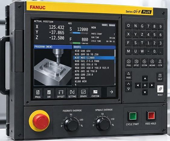
FANUC CNC controls are widely used in machining centers, CNC lathes, and other machine tools. FANUC-style programming is therefore often used as a reference when discussing G codes and M codes.
Common FANUC G-codes include G00, G01, G02, G03, G20, G21, G40, G43, G54, G80, G90, and G91, although the available codes and meanings depend on the specific FANUC control and machine type.
Common FANUC M-codes include M00, M01, M03, M04, M05, M06, M08, M09, and M30. Machine builders may add their own M-codes for functions that are unique to a particular CNC machine.
When searching for a G & M code list for FANUC, it is important to identify the controller model. For example, a FANUC milling control and a FANUC turning control may use the same basic G-code numbering system while assigning different functions to particular commands.
Therefore, a generic FANUC G codes and M codes list is useful for learning, but the machine-specific programming manual remains the best reference for production work.
G-code and M-code for Haas
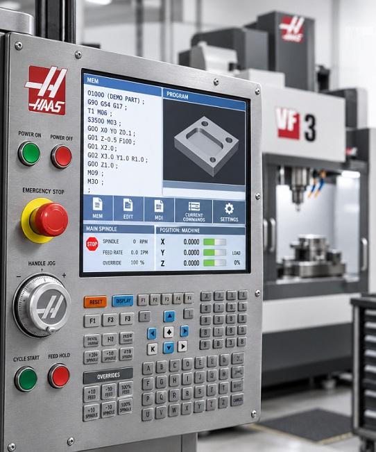
Haas CNC machines use G-codes and M-codes to control tool movement, machining operations, spindle functions, coolant, tool changes, and other machine functions. While many Haas codes follow conventions common to other CNC controls, some codes and functions are specific to Haas machines.
Common Haas G-codes include G00, G01, G02, G03, G17, G20, G21, G40, G41, G42, G43, G54, G80, G90, and G91. Common Haas M-codes include M00, M01, M03, M04, M05, M06, M08, M09, and M30.
The exact codes available and their behavior can depend on the Haas machine model and control configuration. For production programming, always refer to the machine-specific Haas operator or programming manual.
G-code and M-code for Okuma
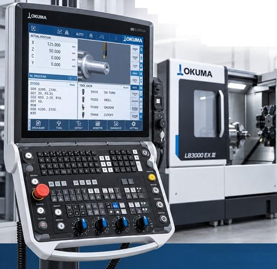
Okuma CNC controls use G-code and M-code programming, but their exact command set and implementation can differ from FANUC and other CNC systems. Okuma machines may use proprietary or machine-specific functions in addition to commonly recognized CNC commands.
Many basic machining concepts remain familiar, including rapid positioning, linear interpolation, circular interpolation, work coordinates, spindle commands, coolant commands, and program-end commands. However, programmers should use the documentation for the specific Okuma control before assuming that a FANUC G-code or M-code has the same function.
This distinction is especially important when transferring CNC programs between machines. A program that runs correctly on a FANUC-controlled machine may require changes before it can be safely executed on an Okuma control.
What are common G-code and M-code errors?
G-codes are relatively standardized, but M-codes are much more controller- and machine-dependent. Fanuc, Haas, Siemens, LinuxCNC, Mach3, and other controls can interpret or support different codes. Common G-code and M-code errors usually come from incorrect syntax, incompatible commands, missing parameters, or machine-state conflicts.
Common G-code errors
- Unknown/unsupported G-code: The controller doesn't recognize a command, such as using a code that isn't supported by that particular CNC control.
- Missing required parameter: A command needs an axis, feed rate, radius, etc., but it isn't provided.
- Invalid axis or coordinate: Using an axis the machine doesn't have or specifying an invalid coordinate.
-
Feed-rate error: A motion command requires a feed rate (
F) but none is active, or the feed rate is outside the controller's allowed range. -
Rapid/feed confusion: Using
G00when a controlled cutting feed (G01) was intended. -
Arc errors (
G02/G03): IncorrectI/J/KorRvalues, an impossible arc geometry, or an endpoint that doesn't match the specified arc. - Modal conflict: Commands from incompatible modal groups are used together, or the machine remains in an unintended mode from an earlier line.
-
Work-offset error: Incorrect or missing
G54,G55, etc., causing the tool to move relative to the wrong work coordinate system. -
Absolute/incremental error: Confusing
G90(absolute) withG91(incremental), potentially producing a large unexpected movement. -
Plane-selection error: Incorrect
G17,G18, orG19selection for an arc or other operation. -
Tool compensation error: Incorrect
G41/G42cutter compensation, missing lead-in/lead-out, or compensation activated in an invalid location. -
Canned-cycle errors: Missing or invalid parameters for cycles such as
G81,G83, orG84.
Common M-code errors
- Unknown M-code: The machine/controller doesn't support the specified M-code.
- Wrong M-code for the machine: M-codes are especially machine-specific; for example, coolant, chuck, pallet, or auxiliary functions can differ between controls.
- Conflicting M-codes: Two auxiliary functions that can't operate simultaneously are commanded together.
-
Incorrect spindle command: An M-code affecting the spindle is used incorrectly or without the necessary spindle-speed (
S) command. -
Coolant errors:
M08/M09or equivalent commands don't match the machine's coolant configuration. -
Program-stop confusion:
M00orM01stops the program when the operator wasn't expecting it. -
End-of-program errors: Incorrect use of
M02/M30, or failing to properly terminate the program. - Door/interlock or auxiliary-device errors: Machine-specific M-codes can fail if the required hardware or machine condition isn't available.
Example
G90 G54          ; Absolute positioning, use work coordinate system G54
G00 X0 Y0        ; Rapid move to X0, Y0
G01 X50 F200     ; Linear move to X50 at feed rate 200
G02 X75 Y25 R25  ; Clockwise arc move to X75, Y25 with radius 25
M08              ; Coolant ON
M30              ; End program and rewind
Possible problems include an invalid R25 arc geometry, an unsupported M08, or a missing spindle command if the machine requires the spindle to be started before cutting.
What is the best G-code software?
The best G-code software depends on what the user needs to accomplish. CNC programming software can range from simple text editors and G-code viewers to complete CAM systems that generate machining programs from 2D drawings or 3D models.
For simple manual programming, a basic editor may be sufficient. For more complex machining, CAM software can calculate tool paths and generate controller-specific G-code. Simulation software can then be used to check the tool path for potential collisions, excessive movements, and other problems.
For CNC machining, Autodesk Fusion is a strong all-around choice for many users. It combines CAD and CAM, supports milling, turning, and mill-turn workflows, and can generate machine-specific NC/G-code through post processors.
| Software | Best suited for | Key features | Free version? |
|---|---|---|---|
| Autodesk Fusion | General CNC machining | Integrated CAD/CAM, good for milling and turning | Yes — limited personal use |
| Mastercam | Professional CNC programming | Widely used professional CAM platform | No — paid software |
| FreeCAD | Free/open-source workflows | Open-source CAD/CAM software | Yes — open source |
| Haas / controller-specific tools | Specific CNC environments | Useful for specific CNC machine/controller workflows | Varies by tool |
G-code and M-code Guidelines
G-code and M-code provide precise control over CNC machines, but they should not be treated as universally interchangeable instructions. The same code number can have different meanings depending on the CNC controller, machine type, software options, and machine builder.
Before running a new CNC program, operators and programmers should verify the controller model, units, work coordinate system, tool offsets, spindle settings, feed rates, machine limits, and expected tool path. The program should also be checked for possible collisions and unexpected movements.
In particular, programmers should be careful when transferring programs between FANUC, Okuma, Haas, Siemens, and other CNC controls. Even when a controller supports standard G-code commands, machine-specific M-codes and cycles may not transfer directly.
G-code and M-code are most effective when used together with accurate machine setup, appropriate tooling, reliable CAM post-processors, and proper program verification. Understanding the difference between the two code families is an important first step for anyone learning CNC programming.